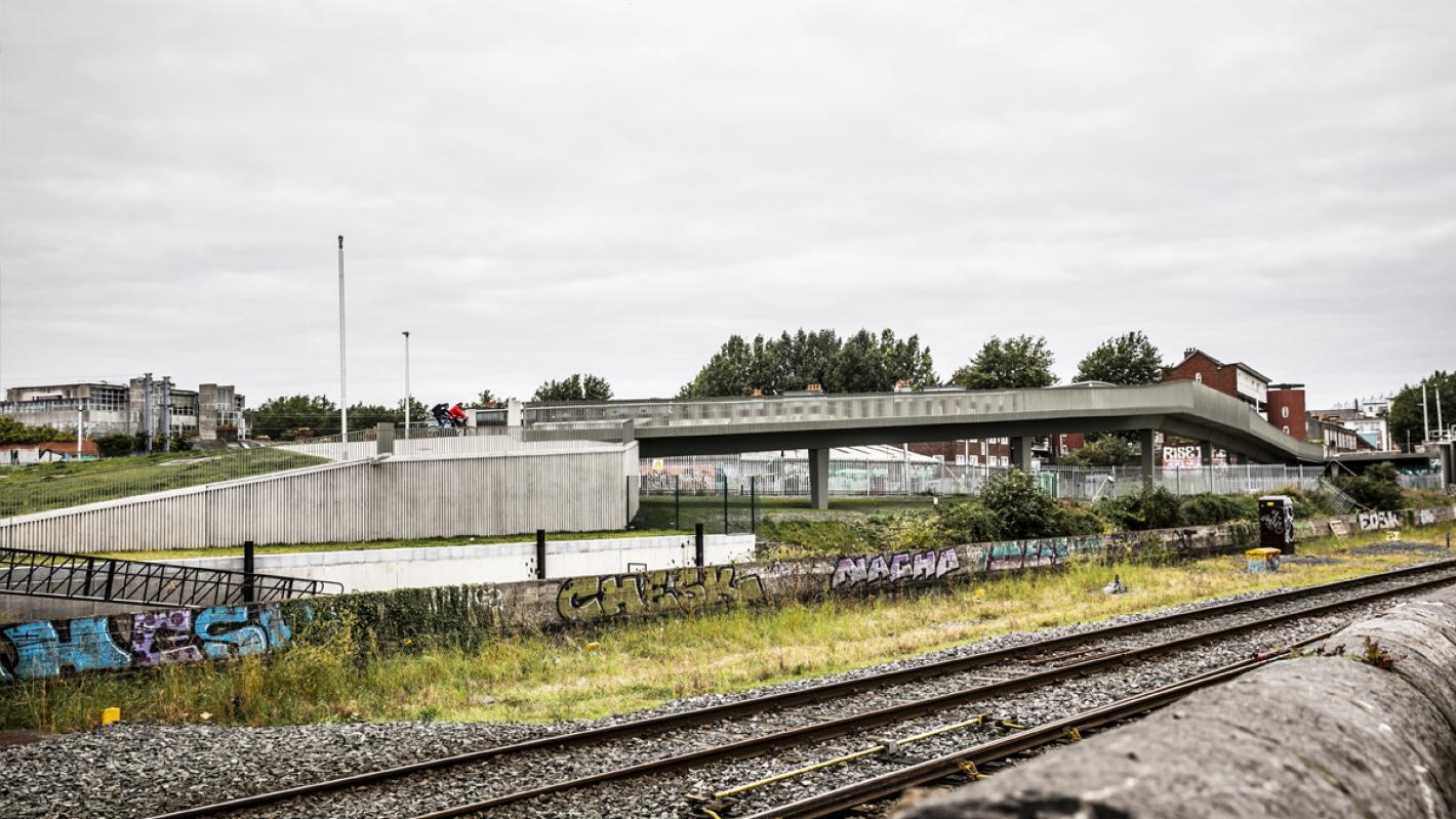
The Royal Canal Viaduct in Dublin's north inner city.
A key component in Dublin City Council’s plan to provide the people of Dublin with a high quality, coherent and sustainable cycle network across the city.

The Royal Canal Viaduct in Dublin's north inner city.
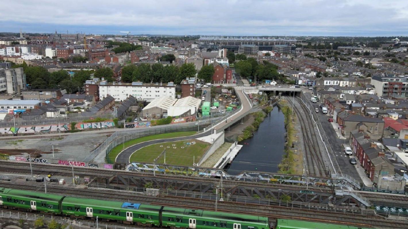
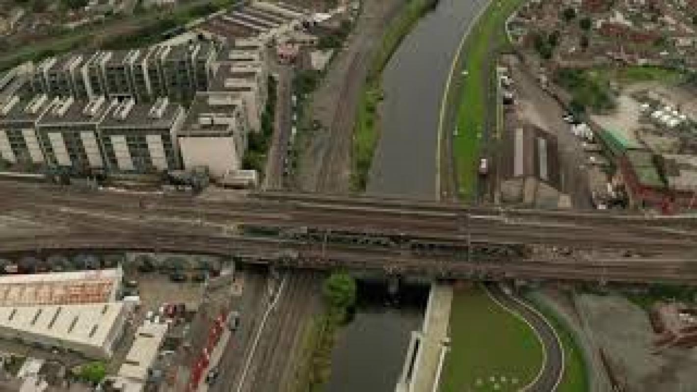
An aerial view of the Royal Canal Phase 2 Viaduct.
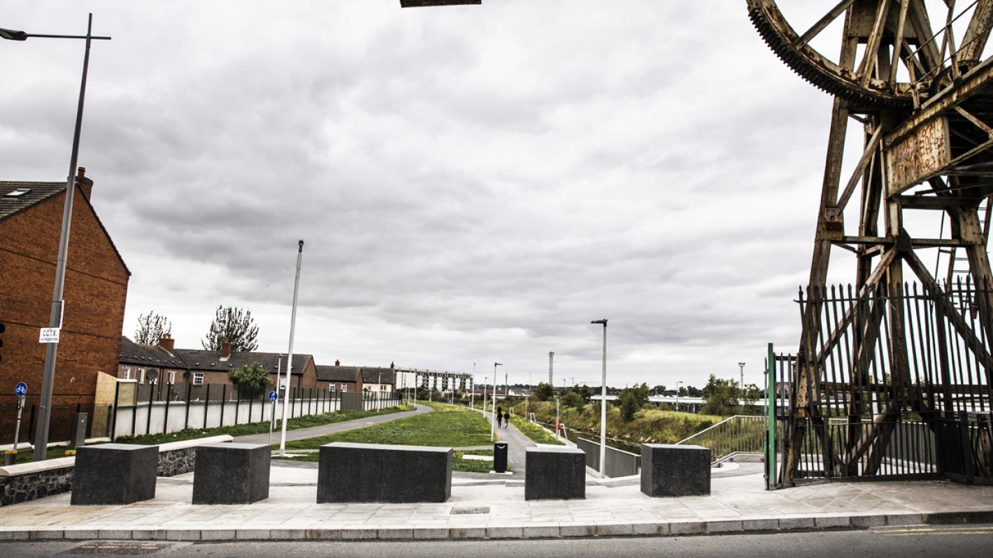
The view of the linear park from the Sherriff Street Lifting Bridge.

The Royal Canal Phase 2 scheme provides a high-quality cycle track, footway and linear park from Guild Street to North Strand Road and includes a multi-span viaduct over the railway. The scheme forms part of the Royal Canal Greenway which, when complete, will provide a first-class, multi-purpose, off-road walking and cycling link from Cloondara on the River Shannon in County Longford through to the River Liffey in Dublin City.
The Royal Canal Phase 2 Viaduct is a critical piece of infrastructure within the Royal Canal Greenway scheme and will enable pedestrians and cyclists to travel from the North Strand Road through to the Seville Place junction unobstructed.
At the western end of the scheme, the North Strand Road side, the viaduct Iinks to the recently installed ROD designed Newcomen Footbridge, which spans over the Docklands Railway Line and the Royal Canal and serves as a pedestrian bridge running parallel to the existing Newcomen Road Bridge.
The viaduct will take pedestrians and cyclists over the Newcomen railway line coming out of Connolly Station and onto a newly constructed, landscaped, winding approach ramp. From here, pedestrians and cyclists will be taken under the main northern line railway bridges and along approximately 500m of newly refurbished bank of the Royal Canal to the Seville Place junction.
Engineers Ireland Excellence Awards 2020 - Highly commended (Engineering Infrastructure and Buildings Category)
The viaduct is 112m in length and consists of seven spans. It is a steel composite structure, with a concrete deck made composite with a steel box girder beneath. The deck is monolithic with six tapering steel piers and supported on bearings at a concrete pier at the support closest to the Newcomen Cycle Bridge and a concrete abutment at its eastern end.
Due to its length, the viaduct could not be constructed in a single length, and the team had to consider, therefore, various constraints when determining the optimum construction sequence. The primary constraint was the requirement to construct the bridge over the live railway.
To de-risk the construction process, the decision was made to install the steel girder overthe railway line first. This meant that as the subsequent steel girders were installed, any issues with regard to construction tolerance could be addressed without impacting the railway line.
The deck for spans either side of the railway corridor are formed with in-situ concrete while the deck over rail is formed with precast concrete, thus reducing work over the live railway.
Delivering a simple, sculptural and elegant bridge solution that worked in harmony with the surrounding streetscape and infrastructure provided a key challenge for the design team of ROD, Grafton Architects, Kevin Blackwood and Kevin Cleary Lighting.
The design team needed to find a way of taking pedestrians and cyclists from the relatively low-lying Newcomen Bridge, over the Newcomen railway line and back down again underneath the main northern line railway bridges supporting the railway coming from Connolly Station.
The solution had to comply with:
Due to the bridge’s close proximity to Connolly Station, the team also had to ensure that the bridge solution did not impact either the train divers’ ability to see the signals located around the site or the cables and ducts in the vicinity.
As part of the initial design process, various bridge types were considered. Ultimately the design team concluded that a bridge with steel piers and composite deck was the most advantageous solution. The use of steel piers and a steel box girder forming part of the deck allowed for the majority of the bridge to be fabricated off-site in a controlled environment which assisted greatly with on-site assembly.
The adoption of steel as the primary bridge component facilitated a slender sinuous bridge solution. The bridge piers were designed to taper vertically to highlight to the observer how they “hold” the girder in place. The main steel girder that forms part of the deck taperes in section to maximise apparent slenderness in elevation. Provision of main steel girder with monolithic piers negates the use of bearings at intermediate support thus reducing maintenance requirement.
A 5.2m wide concrete slab made composite with the steel box girder completes the construction of the bridge. This provides a 4m deck surface for pedestrians/cyclists and 0.6m concrete upstands on either side of the walking surface to accommodate services. As the concrete deck cantilevers over the steel box girder underneath, it creates a drop shadow, highlighting the slenderness of the structure.
When adopting steel components in a bridge structure, providing a satisfactory corrosion protection system is vital. The external face of the steel piers and steel box girder have, therefore, been applied with a robust corrosion protection system in accordance with the relevant requirements.
Knowing that the slender nature of the bridge piers and girder would make it impossible to inspect the internal steel components once it was constructed, the design team took the decision to hermetically seal both the piers and main girder. This proved challenging as the bridge was assembled from pier and girder segments that arrived on-site and were installed at different times.
To overcome this challenge, the designers installed full height diaphragms at the ends of each bridge component, sealing the majority of the bridge components. This enabled the seal for each component to be tested in the fabrication shop prior to arrival on-site. As a result, the only sections of the bridge that needed to be tested on-site were the small sections of the bridge joints located between the full height diaphragms at the end of each bridge component.
To minimise maintenance liability to Dublin City Council, the bridge is made continuous over its length with full connections at each pier reducing the requirement for bearings and joints.